Von Duprin 98 Series Wiring Diagram
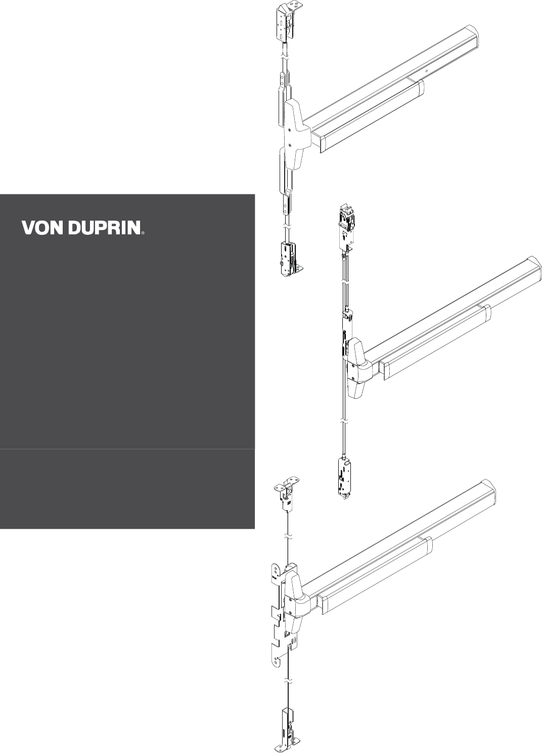
If other 873 logic board, refer to von duprin instructions. 8 • von duprin 98/99 series 98/99 rim exit device 98/99 rim exit device 98 and 99 rim exit devices for all types of single and double doors with mullion, ul listed for panic exit hardware.

Dam links for Inbenta
If available, get a wiring diagram for your installation.

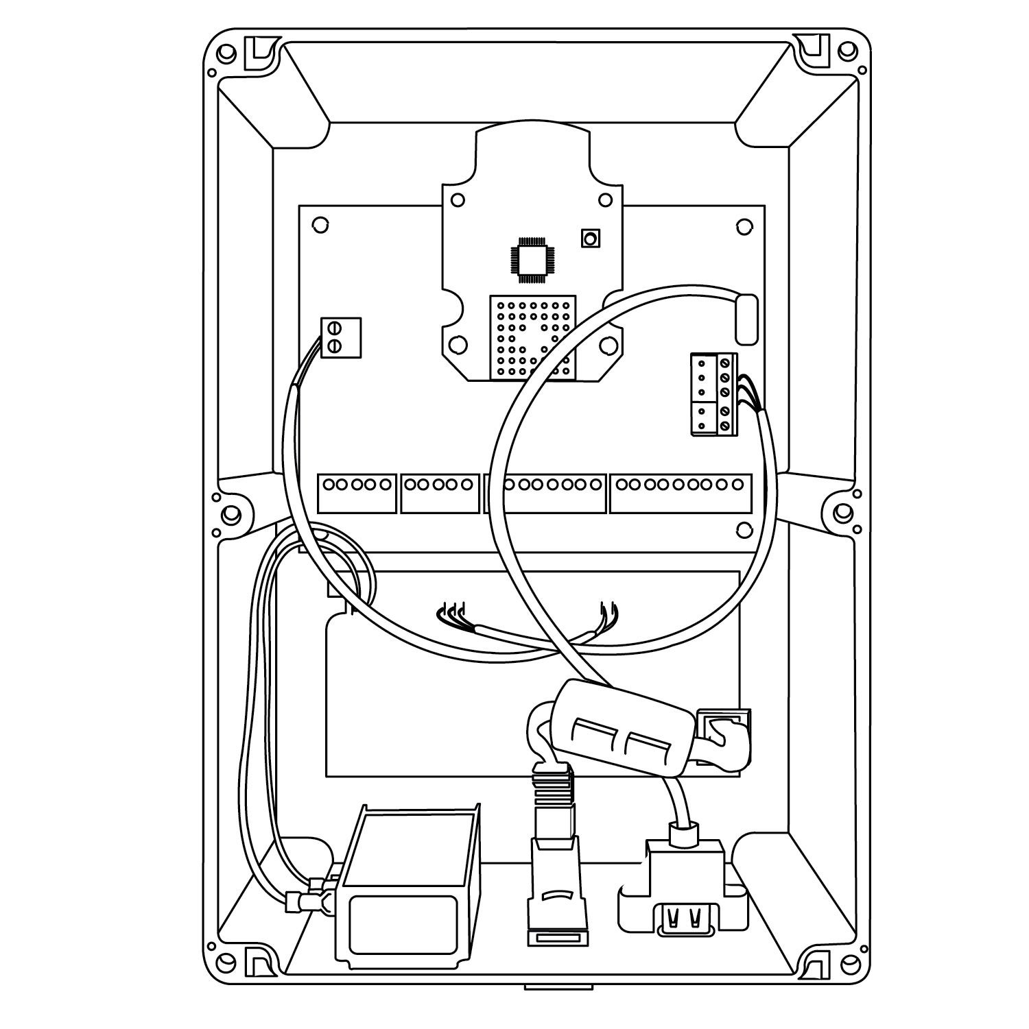
Von duprin 98 series wiring diagram. Otherwise, refer to figures 2 and 3 and table 1 in "typical wiring"and mark the components you use in table 1. Pcb only for the alarm kits prior to june 11th, 2012 is part #650335 and was used in the older 17 & 18 devices, 19, & pre june 2012 24/25's. This circuit board will not work on the updated 24/25 alarm kits that released june 11th, 2012.
Common wiring diagrams can be accessed at. Rba door offers a large selection von duprin 98 and 99 series panic door hardware and 98 and 99 series are designed and manufactured in accordance to ios 9001 quality management system and meet all accepted u.s. " von duprin el wiring diagram.
Description finish 1 1 106224 e98/99rim subminiature switchassembly(r,y,b) 2 1 968938 subminiature switch 3 1. Check with factory for retrofit applications. (von duprin ps873) highly recommended optional required optional (wire multiple.
6 adjust alarm reset time, as needed. Prepare frame for strike (see other side). Von duprin 98 series fax version 911373_00(4) page 8 of 9 drill 5/8"dia.
Deadbolt will not function with this strike. Qel single with ct5000 and mt15 wiring diagram author: In series) optional fire used?
Multiple inhibit devices can be used in series. Post questions, comments, reviews or errors in the comment box below. The von duprin chexit device is designed for controlled egress applications.
If not used, connect green wire to red wire. Schematic for g series lock. Door position switch (nc contacts) provides door position
Von duprin chexit wiring diagram von duprin wiring diagrams wiring diagram is one of the pictures that are related to the picture before in the collection gallery,. The 98 series device has a smooth mechanism case, while the 99 series has a grooved mechanism case. Attached are the single and double door wiring , cable voltage reading documents for trouble shooting, and the installation instructions of the von duprin chexit device.
For lock or device preparation, see their directions. Architectural design elements differ between the 98 and the 99. Exit device options;98/99 series;33a/35a series keywords:
If available, get a wiring diagram for your installation. Von duprin 24 vdc power supply (polarity sensitive input) rx switch lx switch or insulate unused wire insulate unused wire 24vdc ept 10 ei no (normally open) access contol contacts ei tb2 tb1 rx/lx switch nc c no the current draw of a von duprin exit alarm alk is.25 amp when alarm is activated. The following common wiring diagrams are available:
It has two primary applications. The von duprin chexit device is designed for controlled egress applications. Multiple inhibit devices can be used in series.
One single door with panic bar. Description finish 1 1 106224 e98/99rim subminiature switchassembly(r,y,b) 2 1 968938 subminiature switch 3 1. Door position switch (nc contacts) provides door position
If not used, connect green wire to red wire. Von duprin custom wiring diagrams. There are three main failures with.
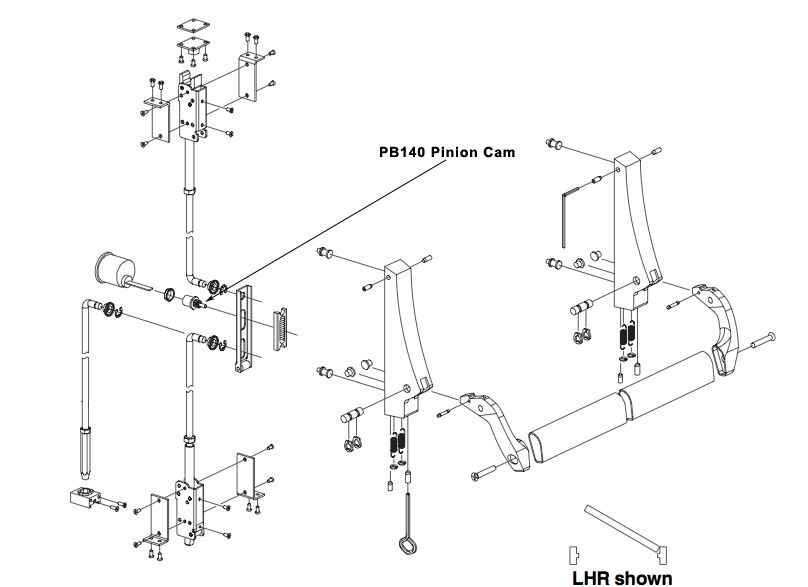
Von duprin 98/9927 5 see "preparation chart" on page 3 for preparation information end cap bracket flush mark and prepare 2 mounting holes level device 8 install end cap bracket and end cap b c secure end cap bracket and end cap 10 11 9 install top latch and rod install top strike adjust top rod (screw rod into or out of latch) until adjusted as shown d top latch top rod. Electric latch retraction, with auto operator; Install after device has been mounted on door do not cut device with potted circuit board installed potted circuit board if the solenoid fails to retract the latch bolt when power is applied, recheck wiring for proper connections.
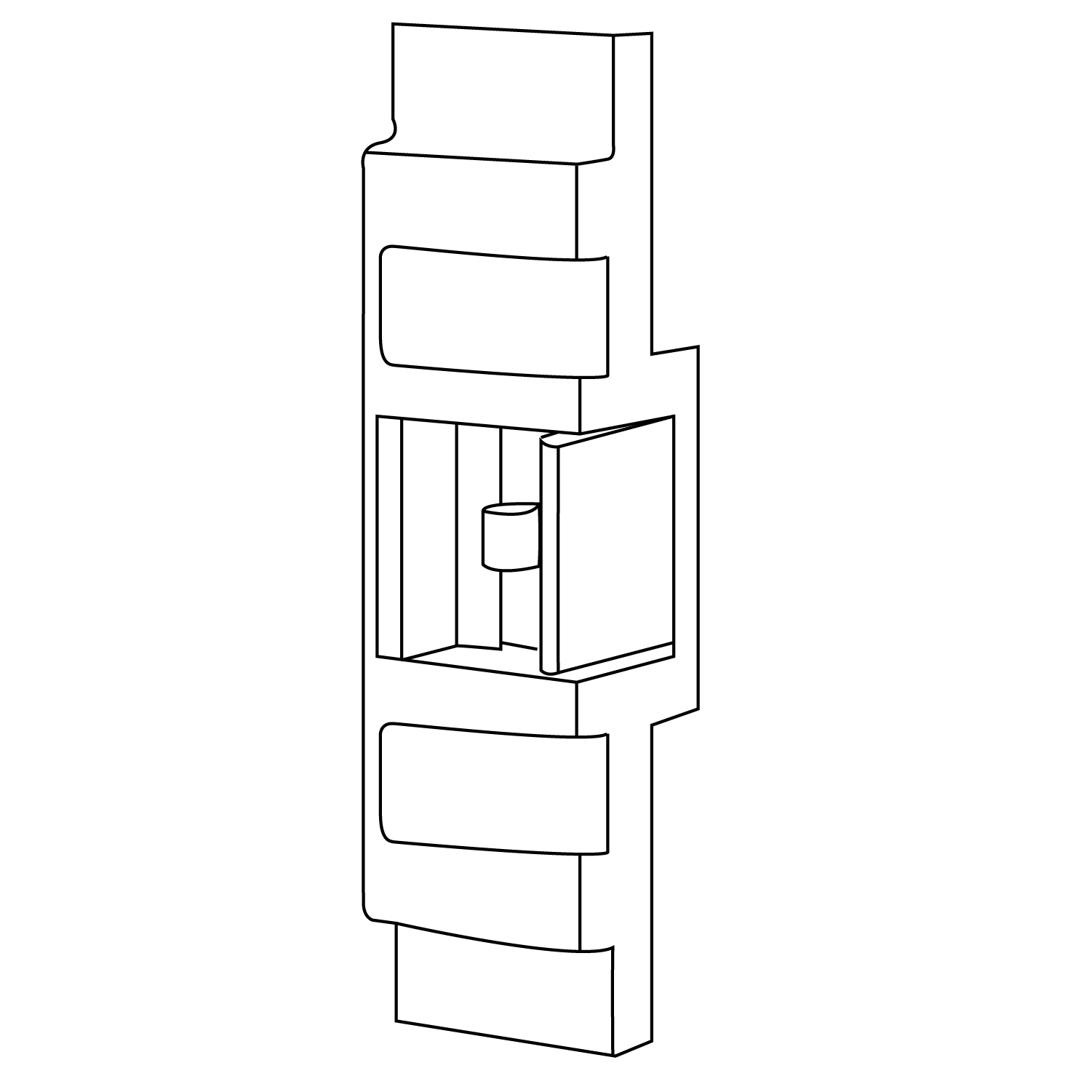
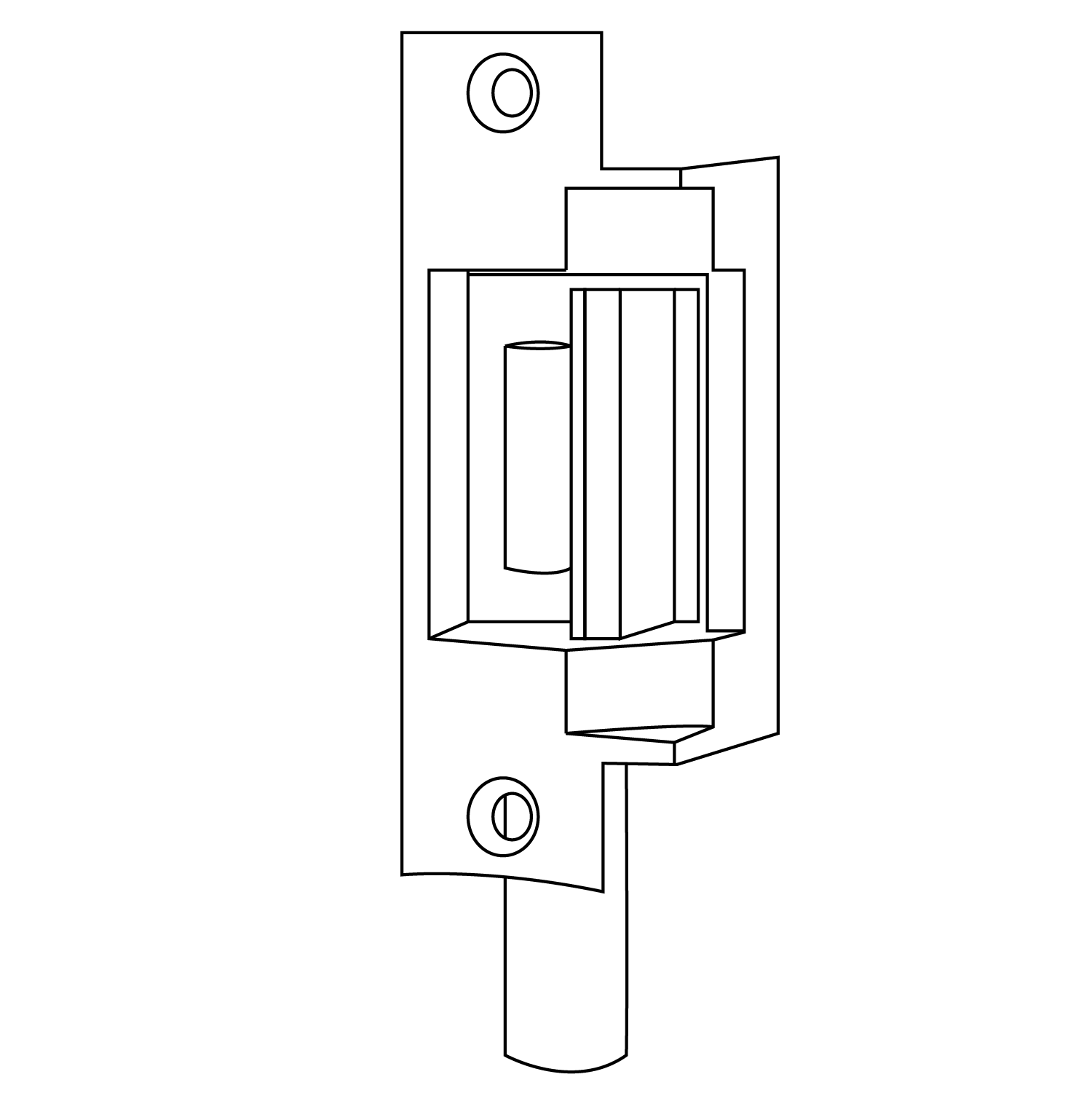
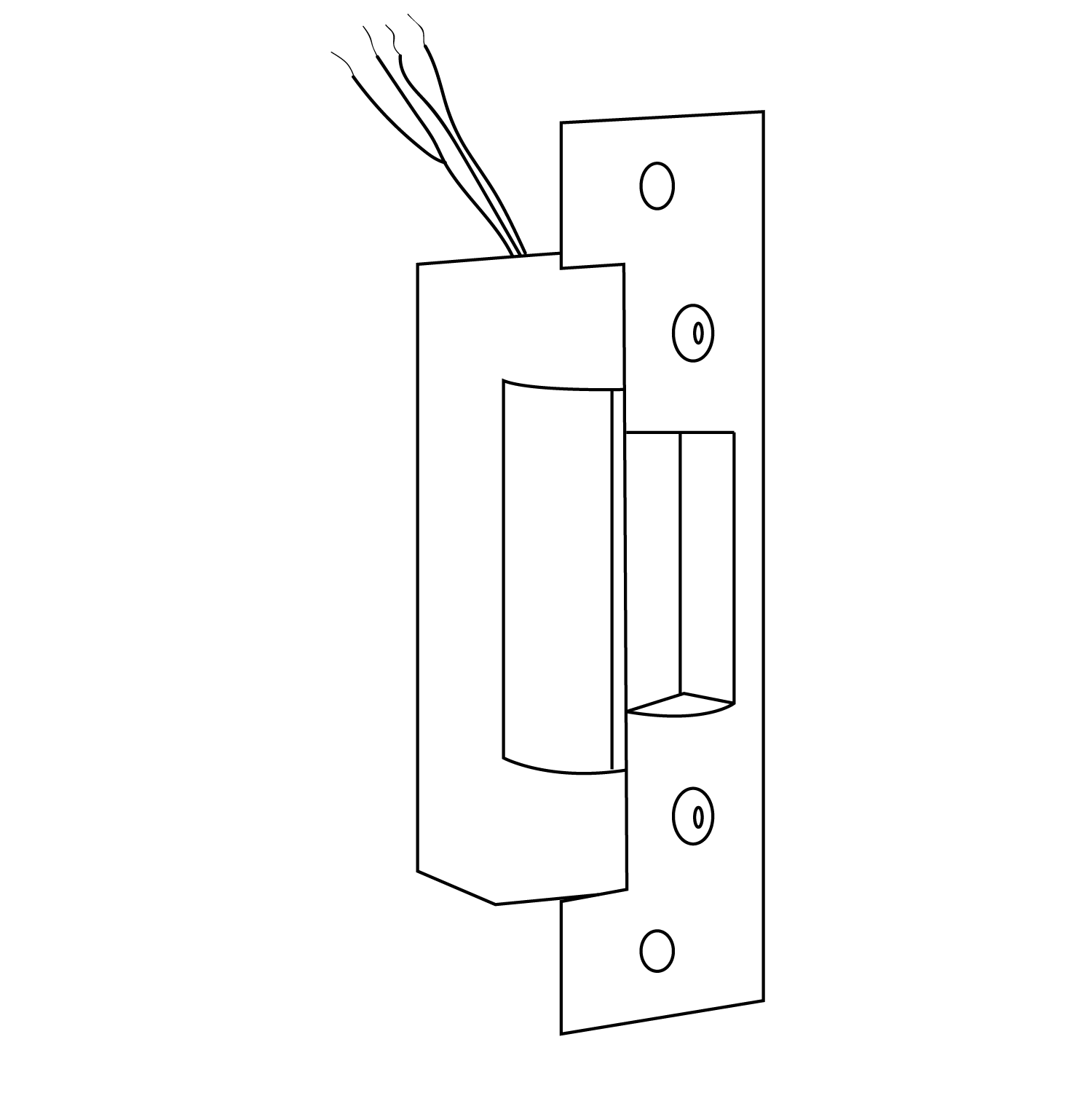
The 98 device has a smooth mechanism case and the 99 device has a grooved case. Wire access hole thru device side of door. Von duprin ® 6211/6211ds electric strike notes:
In series) optional (wire multiple external inhibit devices in parallel) fire. Exit device options;98/99 series;33a/35a series created date: (switches on 6211ds only.) 4.
Install insert for auxiliary bolt operation. Sd option is available and is also standard with von duprin 98/99 rim and vertical rod exit devices but not available with mortise device. Von duprin pool exit hardware.
Wire access hole 5/16" thru device side of door.
Panic Bar Parts Diagram Wiring Diagram

30 Panic Bar Parts Diagram Wiring Diagram Database

VON DUPRIN 374/376/377 050592 US10B Thumbturn Kit

VON DUPRIN 050489 313 35A Mechanism Case 4' Door
Von Duprin 105676 Rev 0415 33/3547A
Dam links for Inbenta
Dam links for Inbenta

Wiring Diagram 33 Panic Bar Parts Diagram
Dam links for Inbenta
30 Panic Bar Parts Diagram Wiring Diagram Database

Wiring Diagram 33 Panic Bar Parts Diagram

30 Panic Bar Parts Diagram Wiring Diagram Database
Dam links for Inbenta
Dam links for Inbenta

ALK Alarm Kit ALK Installation Instructions for Series 33

Dam links for Inbenta
Power Supply Von Duprin Power Supply


Panic Bar Parts Diagram Wiring Diagram

Von Duprin Price Book 2017